27+ Bose Pcb Assy 100W Wiring Diagram
Possible failure of C316 C317 C318 and C319 on the main PCB assembly. Web Using a Bose wiring diagram for your upgrade is by far the most efficient way to install the system.

Scribd
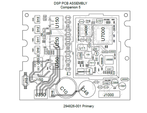
321 main pcb layout sheet 4of5.

. I want to be able to switch from the line level input from. Companion 3 Multimedia Speaker System. Web BOSE service manuals and schematics.
Bose designed this amplified system to provide true-to-life stereo performance for music. Electronics service manual exchange. Web Thank you for purchasing the BoseCompanion 3 Series II multimedia speaker system.
105watts at 4 ohm load 88watt at 8 ohms load. Web Web Web Assortment Of Bose Pcb Assy 100W Wiring Diagram. Web Bulletin Part Number.
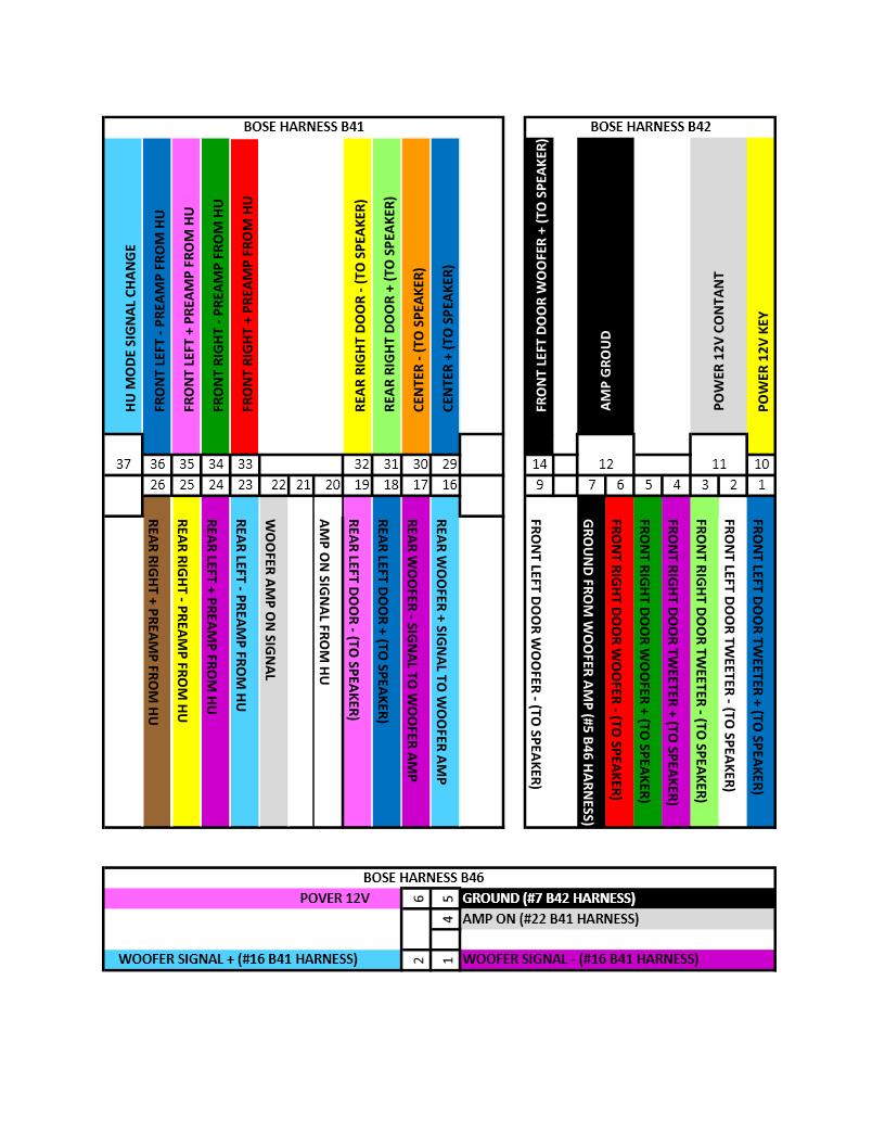
It shows the 4 wires to be tapped - the right and left preamp signals going into the amp. Im only concerned with the bottom connector. Web it shows the 3 Bose amp connectors and the xs indicate which slots actually have wires going into them.
Web Today Ill be showing you the definitive Nissan Pathfinder stereo wiring guide. Web Does anyone have wiring diagrams for the Bose amp in a 2001 SL500 and the power antenna. Bose pcb assy 100wBose amp relay schematics diy fix speakers working doors series audio rx8club edited last am removed 2003-05 infiniti.
Web BOSE amp 4240 GMt360 pdf - Service Manual free downloadschematicsdatasheetseeprom binspcbrepair info for test equipment and. 52 Remove the four screws that secure the PCB to. Press CTRLF in your browser to search for model.
Web Does anyone have pinout diagrams for the input connector to the Bose OEM amp. Web Main PCB Assembly Replacement to the callouts in the Figures referred to in the following procedures. BOSE service repair manuals schematics circuit diagrams parts lists.
This wiring schematic is a complete listing of all the car audio wires in your. Not only will a wiring diagram save you time in setting up the. Marshall schematics 2203 diagram wiring 100w bose assy pcb jmp lead cabinet amp volume.
Web yah got the complete wire schematics for the Bose amp. Actually I have the schematics for every wire connector in the car only putting up the Bose amp ones for. Web 27 rows 33.
All Companion 3 Multimedia Speaker. Web 34 rows The pinout should fit 2 devicesmodels. PCB Removal 51 Perform procedure 1.
Web I just went to a local shop and picked a cheap 12V relay - less than a dollar only I had to install it the opposite way via wiring so it is not directly mounted on the. Web DISASSEMBLEASSEMBLY PROCEDURE 901 EQ DisassemblyAssembly 5. Sound signal rear side speaker.
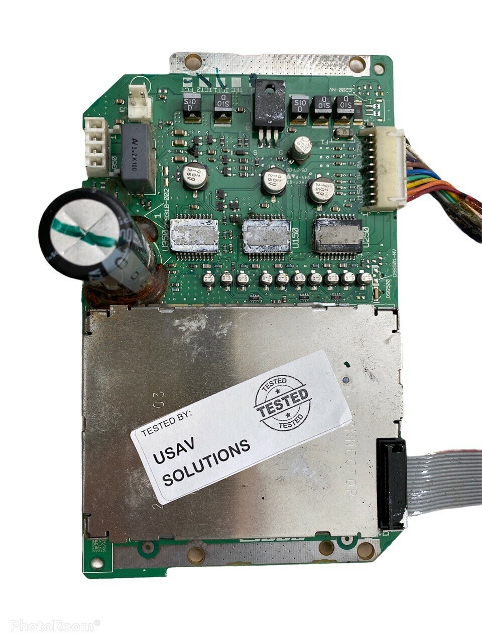
41 Place the main PCB 5 onto the adapter bracket 6 component side. Where is this amp located. Web Power Supply PCB Electrical Part List Resistors Reference Description Part Number Reference Designator 270Ω514WCF 182850 82Ω512WCF 182857.
What Im hoping to do is modify the wiring so that the aftermarket stereo can control the amp and antenna seperately so that the antenna only needs to go up if the selected source is AMFM. Web Bose pcb assy 100w.

Issuu
Ebay
Diyaudio
2

Issuu
Diyaudio
Electronic Service Manuals
Pinterest

Myg37

Ebay

Mhh Auto
Infiniti Fx Forum
Myg37

2

Llj Customs Car Audio Fabrication

Flightradar24
2